Creating a shift register to transfer bits over a line

The favorite HDL language in North America

Creating a shift register to transfer bits over a line

Postby dstegs » Sat May 29, 2010 1:34 am

Hi,
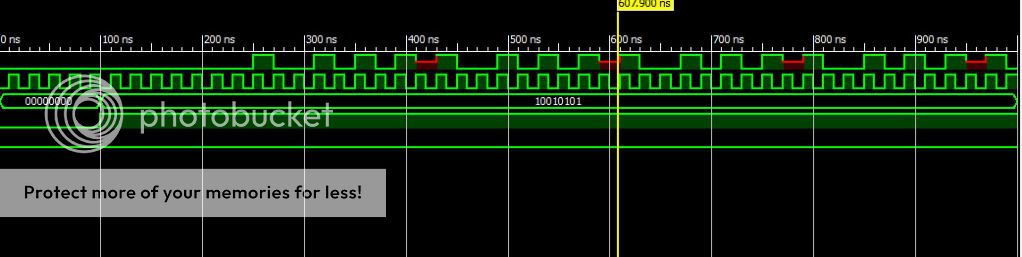
I created a shift register to transfer bits from my spartan 3e to another spartan 3e. I'm using the following code to shift.

Code: Select all
module TX_Shifting(Clk, Data_in, Data_out, enable, Reset);
input Clk,enable,Reset;
input [7:0] Data_in;
output Data_out;

reg [7:0] tmp;
reg [7:0] counter;

initial counter = 0;
initial tmp = 0;

  always @(posedge Clk)
    begin
    if (Reset)
    begin
   tmp=0;
   counter=0;
    end
    if (enable)
       begin
          tmp = tmp << 1;
          tmp[0] = Data_in[7-counter]; //sends MSB first
      counter = counter +1;
      if (counter>8) counter=0;
       end
    end
       
    assign Data_out = tmp[7];

endmodule


My question is regarding shift registers. If I changed the shift from <<1 to <<2 will the output of my module miss every other bit because it inserts two zeros prior to updating my output variable? Or does it work differently. Also, a question about the recieving board. Should I recieve all 8 bits from Master module prior to updating the config on the Slave board? Or do you think it's fine to just update on the fly.

Any advice on trying to tranfer data is welcome. :D

Thank you,
Daniel
dstegs
 
Posts: 3
Joined: Sat May 29, 2010 1:21 am

Timing diagram for my shift register

Postby dstegs » Sat May 29, 2010 5:57 am

My timing diagram has red sections which i'm assuming are errors. Any advice on how to adjust my code to fix my timing erros? My diagram is below.

[img]
http://i438.photobucket.com/albums/qq10 ... timing.jpg
[/img]
dstegs
 
Posts: 3
Joined: Sat May 29, 2010 1:21 am

Postby NickH » Sat May 29, 2010 12:22 pm

The red sections represent "X" values. These are bits that are not properly defined (typically because they've been assigned two different values at once, or they're functions of unconnected inputs).

I think your problem here is "tmp[0] = Data_in[7-counter];". When counter is 8, this will give Data_in[-1], which is undefined.

Yes, the shift operator works like you describe. But the shift register is just acting as a delay here: you're putting bits in one end and taking them out the other. The real work of breaking the byte into bits is being done by Data_in[7-counter].

P.S. How to transfer data? It can be tricky. It depends on how many wires you have available, how fast it can go, and whether the FPGAs share a clock or have separate clocks...
There's a loosely defined protocol called SPI (google this) which might be what you want. To make it reliable between two boards you'll need to generate a slow serial clock (e.g. max 1MHz), resynchronize inputs to your internal clocks, and make sure you read and write bits near the opposite edges of the serial clock (to avoid skew issues).
Alternatively, consider a UART, you should be able to find some IP on the web, maybe here.

P.P.S. Before you make your design any more complicated, learn to use the "<=" (delayed assignment) operator inside clocked blocks. Otherwise, you might encounter trouble (so-called race conditions) when simulating multiple "always @(posedge Clk)" blocks (of course that still won't help you with real-world inter-board timing issues).

Regards,

Nick
NickH
 
Posts: 88
Joined: Tue Sep 02, 2008 1:53 pm


Return to Verilog HDL